NOT FINISHED
Technical information about drum brakes appears to be a little light on the Internet so here's a bit of background on the theory of them. It was mainly written with cars in mind but the principles for a motorcycle are the same if not simpler due to the lack of a parking brake. One bike, a vintage MZ always had problems with the rear brake locking on when it was cold, understanding this theory explains why and point the way to solving the problem with a file and a face mask!
WHAT IS A DRUM BRAKE?
A drum brake for road vehicles consists of a number of lined shoes located within a drum that rotates with the wheel. To slow or stop the vehicle the shoes are pressed against the inside surface of the drum to create a friction force. For light vehicles, service brake shoe actuation is by one or two hydraulic cylinders. This may be supplemented by a cable operated mechanical expander for parking. The parking brake mechanism shares some of its components with the automatic adjustment system with is used to maintain running clearance as the linings wear.
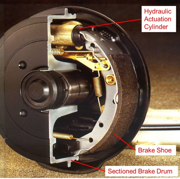 Hydraulic Drum Brake
For heavy vehicles, actuation is by compressed air chambers, operating double-sided cam or wedge mechanisms. Whilst this mechanisms have many similarities, cam brakes force both shoes to travel an equal distance whereas wedge or hydraulic actuators apply equal forces to the shoes. This affects the wear characteristics of the brake.
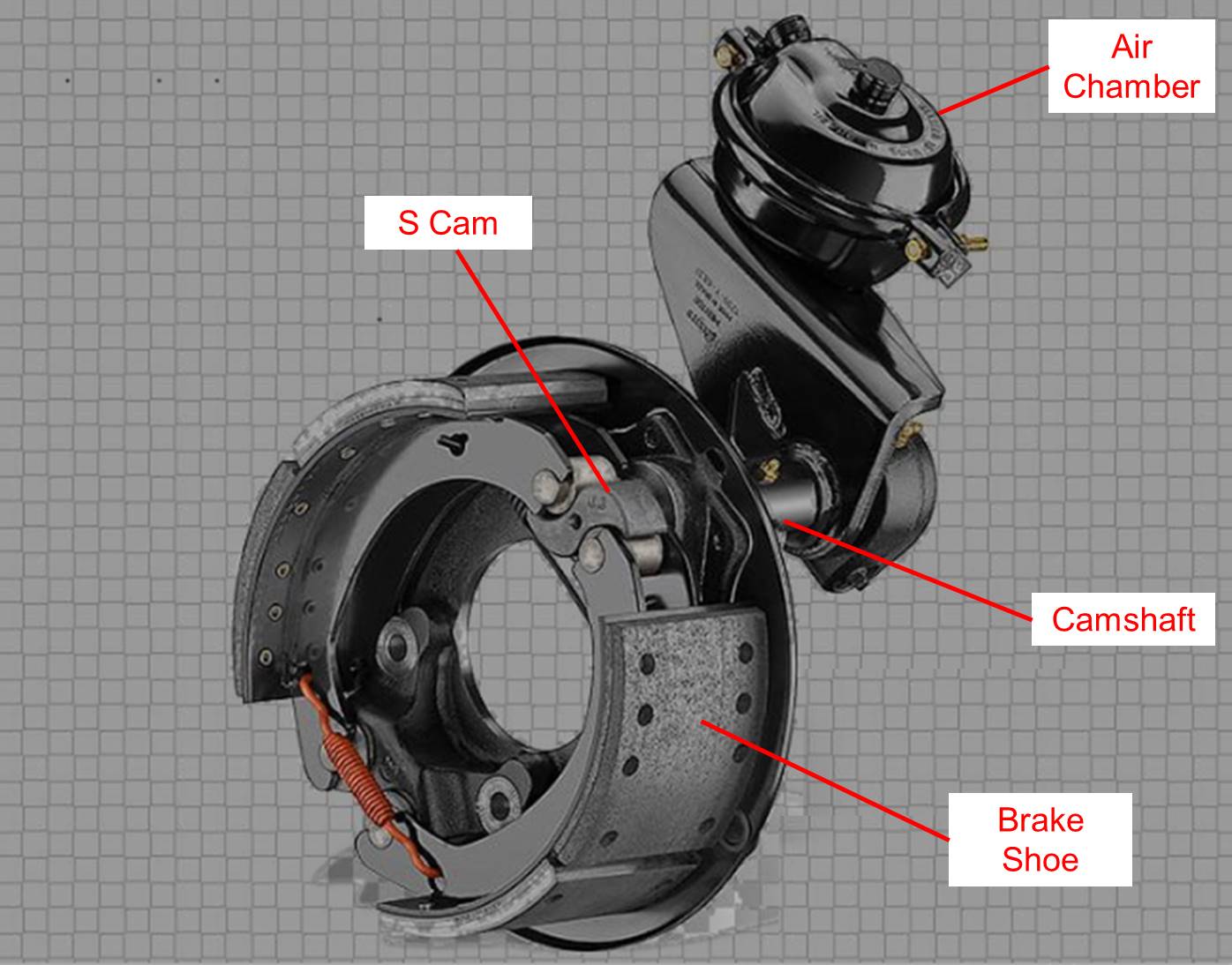 S-Cam Drum Brake
A drum brake for road vehicles consists of a number of lined shoes located within a drum that rotates with the wheel. To slow or stop the vehicle the shoes are pressed against the inside surface of the drum to create a friction force. For light vehicles, service brake shoe actuation is by one or two hydraulic cylinders. This may be supplemented by a cable operated mechanical expander for parking. The parking brake mechanism shares some of its components with the automatic adjustment system with is used to maintain running clearance as the linings wear.
For heavy vehicles, actuation is by compressed air chambers, operating double-sided cam or wedge mechanisms.
Correct drum brake geometry is important in order to ensure that:
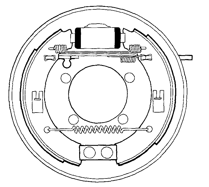
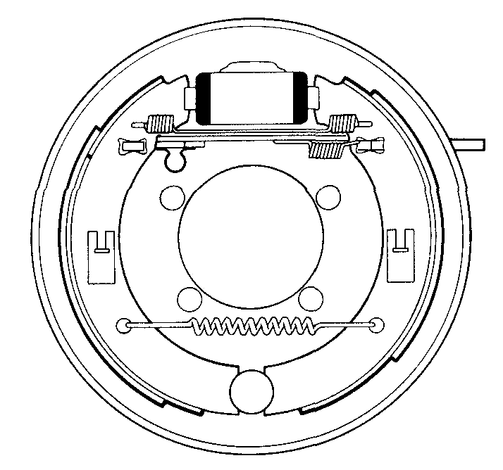
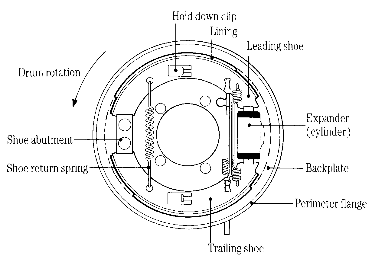 The major drum brake components
LEADING AND TRAILING SHOES
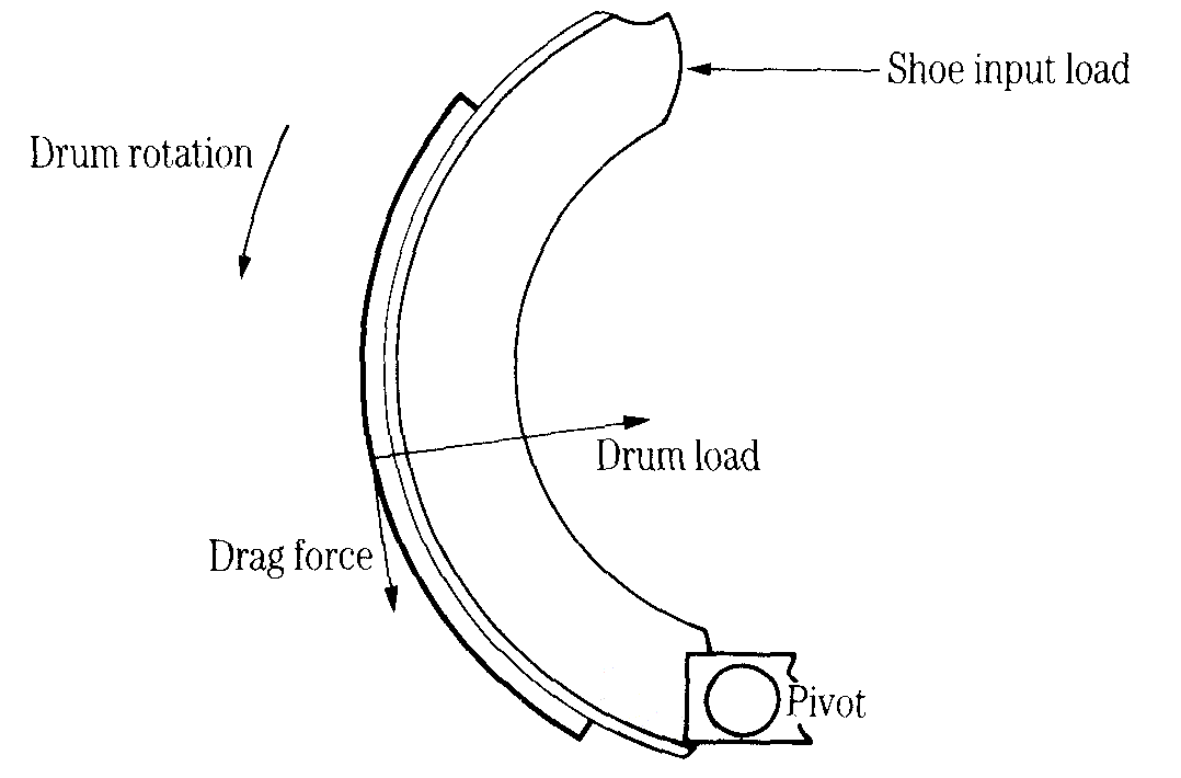
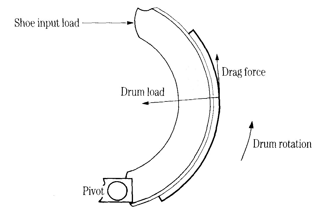
From Figure 1 you will see that, with the drum rotating in the direction shown, the upper shoe is ahead of its pivot point. It is said to be a leading shoe. Similarly the lower shoe trails behind its pivot point and is called a trailing shoe. There is an important difference in the way leading and trailing shoes act under braking.
Figure 2 shows the forces acting when a leading shoe is applied. Notice that the frictional drag force has a moment about the pivot point. This increases the input load and hence increases the drag. In other words, there is a self-servo action, which increases the braking effect.
 Leading shoe
Figure 3 shows the forces acting when a trailing shoe is applied. In this case the moment of the frictional drag force about the pivot point opposes the input load, thereby reducing the drag and the braking effect.
 Trailing shoe
PINNED AND SLIDING SHOES
One end of each shoe locates at a fixed point on the brake back plate. This is done in one of two ways:
Sliding shoes give a degree of self-alignment so the linings can be ground to the drum diameter during manufacture without the risk of the shoes grabbing. This also means that the bedding-in period is relatively short.
 Sliding shoes
In contrast the pinned shoe brake (Figure 5) must have its linings crown ground, i.e. ground to a smaller diameter than the drum. This ensures that the centre of the lining always touches the drum first, until the lining is fully bedded in. If the leading edge of the leading shoe were to touch the drum first the brake would grab. The principles of 'grabbing' is explained later.
 Pinned shoes
BASIC FORCE RELATIONSHIPS
The geometry of a drum brake is determined by the relationships between the various forces acting when the brake is applied. The most fundamental of these are:
Coefficient of friction
When two surfaces in contact have relative movement their coefficient of friction is defined as: COF = friction force opposing relative movement / load perpendicular to the sliding surfaces As far as drum brakes are concerned the coefficient of friction is: COF=drag force / drum load Its value depends on:
If $ax^2+bx+c=0$ with $a≠0$, then:
$$x={-b±√{b^2-4ac}}/{2a}$$